
Understanding technology behind self-driving cars: Stereo Vision

For a long time, self-driving cars were found only in science fiction movies and series but now they are becoming a reality. The opportunity to pick such a vehicle at a car showroom near you is closer than you think.
Autonomous vehicles are becoming more and more popular. Driver assistance systems like adaptive cruise control, lane departure warning, drowsiness detection, self-parking and many more support the driver and help to reduce the number of accidents.
For autonomous vehicles in complex scenarios, environment perception, that too very accurately and quickly, is a very important task, e.g., for detecting objects or other traffic participants or for determining its own position in the surrounding world.
Autonomous systems are usually equipped with multiple sensor types such as radar sensors, ultrasonic sensors, and particularly cameras to cover as much of the environment as possible. Compared to widely used LiDAR-based mapping in the autonomous driving field, image-based mapping methods have the advantages of low cost, high resolution, and no need for complex calibration. Furthermore, they provide visual information similar to human eyes.
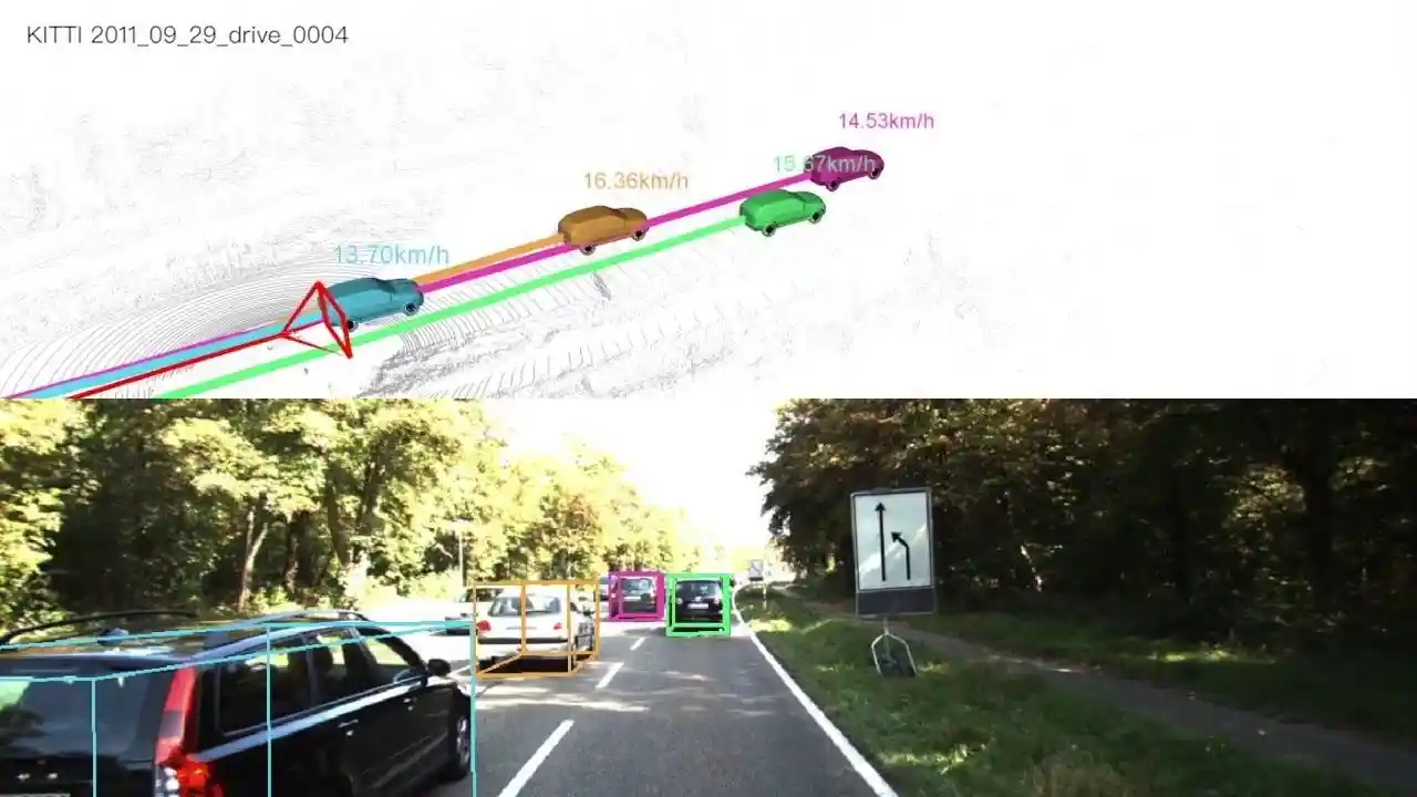
Hence, Stereo Vision, which is the technique of obtaining depth information and 3D geometry from images alone has been introduced, as we can also see in the image below. For this, two images are used, which are generally captured from two different cameras placed on a fixed rig, separated by some distance.
Img: Depth Perception in Self-Driving Cars
Introduction
Computer vision is one of the toughest problems in Artificial Intelligence (AI) that has been challenging researchers and engineers for decades. This problem of extracting useful information from images and videos finds application in a variety of fields such as robotics, virtual reality, autonomous vehicles, etc.
Autonomous navigation has attracted an unprecedented level of attention within the intelligent vehicles community over the recent years. The concept of making cars drive by themselves has gained immense popularity today in the AI world, mainly motivated by the number of accidents that occur due to driver errors. Autonomous vehicles are designed to sense their surroundings and identify its position, velocity & the obstacles around it. The vehicle can then decide what it has to do given the situation it is in.
Stereo vision refers to the task of obtaining depth information or reconstructing a 3D shape from two calibrated overlapping images. The images can be obtained using two cameras placed at some distance or one moving camera.
Stereo Vision for Self-Driving Cars is becoming more and more popular these days, especially for obstacle detection. One of the essential problems in self-driving cars is to identify objects around them. Obviously that’s crucial for a car to navigate its environment. Obstacle detection algorithms provide 2D Bounding Boxes giving the obstacles’ position in an image. Today, most object detection algorithms are based on monocular cameras and cannot return the distance of each obstacle.
To return the distance of each obstacle, engineers generally fuse the camera with LiDAR (Light Detection And Ranging) sensors that use lasers to return depth information. Outputs from Computer Vision and LiDAR are fused using Sensor Fusion. The problem with this approach is the use of LiDAR, which is expensive and energy inefficient. The common belief was that you couldn’t make self-driving cars without LiDARs.
But, recent research has proved that it is not completely true. They align two cameras and use geometry to define the distance of each obstacle: which we also know as a Stereo Camera setup. They rely on two perspectives to establish depth, just as human eyes do. They can achieve the same (or even more) accuracy as Lidar sensors, which makes them a viable and low-cost alternative to LiDAR.
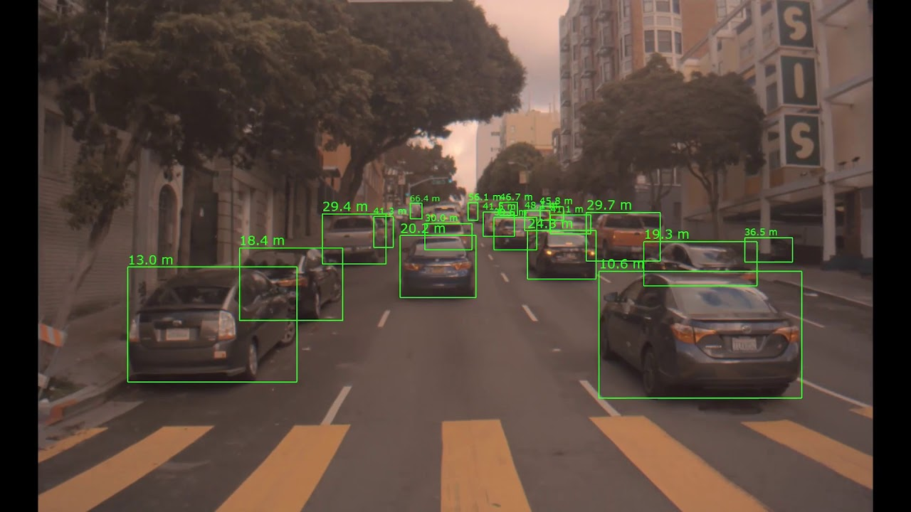
You can see the difference between monocular vision and stereo vision in the image below.
Img: Monocular vision vs Stereo vision
Image-based methods provide a fast way of capturing accurate 3D content at a fraction of the cost of other approaches like radars and lidars. The steady increase of image resolution and quality has turned digital cameras into cheap and reliable high resolution sensors that can generate outstanding quality 3D content.
Hence, stereo cameras are crucial sensors for self-driving vehicles as they are low-cost and can be used to estimate depth. Accurate estimation of dense depth maps is a necessary step for many problems such as obstacle detection, free-space detection, localization, mapping, path planning and lane boundary detection.
Let us first try to understand more about what Stereo Vision actually is.
What is Stereo Vision?
Gathering depth information and reconstructing 3D geometry from photographs is a classic Computer Vision problem that has occupied researchers for more than 30 years. Only recently however have these techniques matured enough to exit the laboratory controlled environment into the wild, and provide industrial scale robustness, accuracy and scalability.
Stereo vision is the process of extracting depth information and 3D geometry from passive 2D images captured by stereo cameras without the need for dedicated active light-emitting range measurement devices like Lidars. Stereo vision is used in applications such as advanced driver assistance systems (ADAS) and robot navigation where it is used to estimate the actual distance or range of objects of interest from the camera (or vehicle).
In simple words, binocular stereopsis, or stereo vision, is the ability to derive information about how far away objects are, based solely on the relative positions of the object in the images obtained from the two cameras, which imitate the two eyes in humans. So, a stereo camera comes with two image sensors (cameras) to simulate human binocular vision, giving it the ability to perceive depth. This is similar to the biological process of stereopsis in humans.
The goal of a stereo vision algorithm can be described as “given two photographs of an object or a scene, gather depth information and estimate the most likely 3D shape that explains those photographs, under the assumptions of known materials, viewpoints, and lighting conditions”.
Generally, in stereo vision technique, two cameras which are positioned parallel to each other are employed to see the same object. The two cameras are displaced horizontally from one another and are used to obtain two differing views on a scene.
The two cameras are separated by a baseline, the distance between the two lenses, which is assumed to be known accurately. The two cameras simultaneously capture two images. The two images are analyzed to note the differences between the images. Essentially, one needs to accurately identify the same pixel in both images, known as the problem of correspondence between the two cameras.
Features like corners can be easily found in one image, and the same can be searched in the other image. Alternatively, the disparity between the images can be found to get the indicative regions in the other image, corresponding to the same regions in the first image, for which a small search can be used. The disparity helps to get the depth of the point which enables projecting it in a 3D world used for navigation.
In a nutshell, to compute depth based on the binocular disparity between the images of an object obtained from the left and right cameras, the system matches features in the two images, that is, identifies features of the same point in the left and right images of the visual scene. So, 3D information can be extracted by examining the relative positions of objects in the two images.
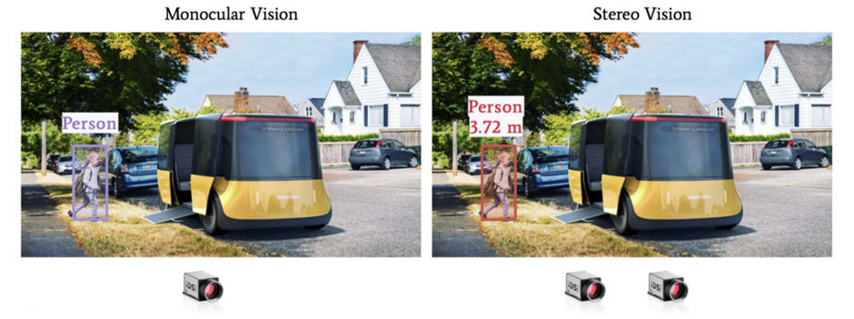
The camera setup used to obtain stereo images for stereo vision is generally known as stereo camera setup. We can see an example of stereo camera setup (left) and stereo images (right) in the image below.
Img: (a) Stereo Camera System (b) Stereo Images
There are generally two types of stereo camera setup :-
1. Passive Stereo:
- The Passive Stereo system depends on the available light in the environment and doesn’t employ any kind of external light.
- Pros: Performs well in sunlight and Cost Effective
- Cons: Mediocre performance in low light and non-textured scenes
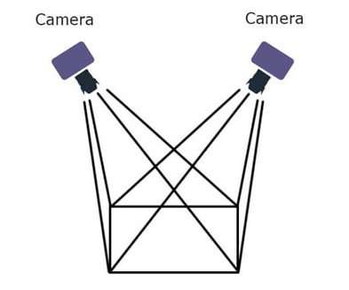
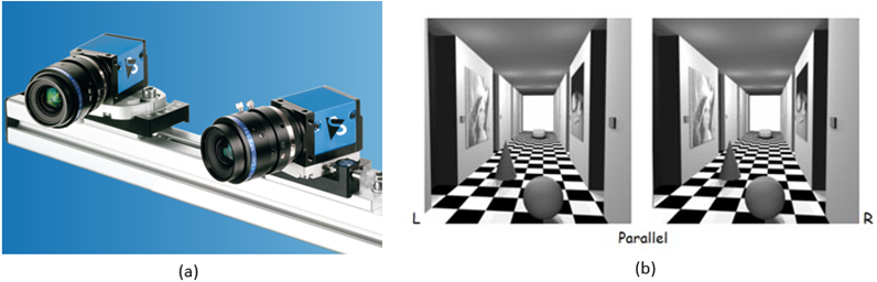
Img: Passive Stereo Setup
2. Active Stereo:
- The active stereo vision is a form of stereo vision which actively employs a light such as a laser or a structured light to simplify the stereo matching problem.
- Active stereo is useful in regions where there is a lack of light and/or texture. The infrared projector or another light source will flood the scene with texture thereby cutting off the dependency of an external light source.
- But along with its positives, there are some negatives such as active stereo will lose its effectiveness in direct sunlight and in regions with a high interference of the same external light source technology used.
- Pros: Performs well in low light and non-textured indoor scenes.
- Cons: Under sunlight and over long-range, it is the same as passive stereo. Also, IR projector adds to cost.
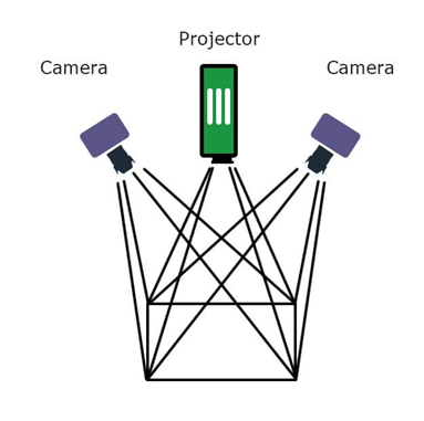
Img: Active Stereo Setup
You can learn more from here: Clumsy Cyclops- How does Stereo Vision work? Stereo vision based semantic 3D object and ego motion tracking for autonomous driving
Stereo Vision is one of the most important components of 3D reconstruction and is also used in many other applications such as 3D movie recording & production, object tracking, machine vision, range sensing, 3D mapping & navigation, 3D printing, computer video games, autonomous driving and cultural heritage archival. It has also been shown in several cases that stereoscopic vision can be applied to extract useful information about the surroundings that could assist the navigation of mobile robots.
Now let us try to understand how we can achieve stereo vision.
How is Stereo Vision Achieved?
Stereo Vision is about finding depth based on two images. Our eyes are similar to two cameras. Since they look at an image from different angles, they can compute the difference between the two points of view and establish a distance estimation.
Similarly, from 2 cameras, we can estimate the depth and retrieve the distance of an object. This is the principle of triangulation, and this is the core geometry behind Stereo Vision. This is done in 5 simple steps:
1. Stereo Calibration:
- Calibration means converting a 3D point (in the world) with [X,Y,Z] coordinates to a 2D Pixel with [X,Y] coordinates.
- The goal is to retrieve the key parameters from the camera
- You can also see the calibration process in the image below for better understanding.
Img: Calibration Process
- Generally, a checkerboard and automatic algorithms are used to perform calibration. When we do it, we tell the algorithm that a point in the checkerboard corresponds to a pixel in the image.
- First, images of the checkerboard are taken with the camera, and after some images and some points, a calibration algorithm will determine a calibration matrix for the camera by minimizing a least square loss.
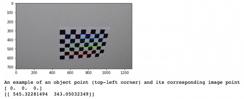
- Generally, calibration is necessary to remove image distortion. So, calibration helps to undistort an image.
2. Epipolar Geometry:
- In this step, we define the 3D Geometry of our setup
- In a stereo setup, we have two cameras, generally aligned on the same height.
- We have two cameras, a left and a right one. These two cameras are aligned in the same Y and Z axis. Basically, the only difference is their X value.
- You can see an example in the image below where we have two cameras CL (camera left) and CR (camera right) looking at an obstacle O. With geometry, we can find its distance.
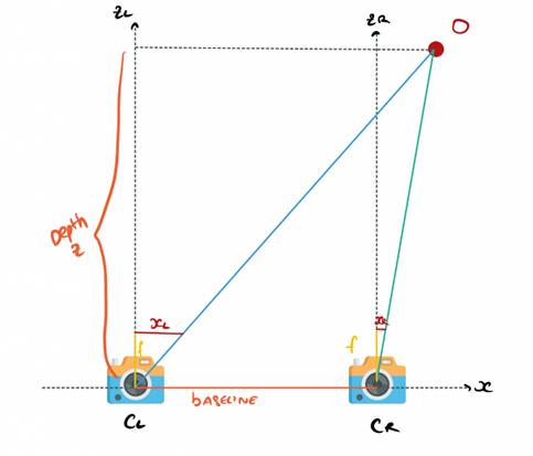
Img: Stereo Setup
- Our goal is to estimate the Z value, the distance for the O point (representing any pixel in an image).Here, X is the alignment axis, Y is the height and Z is the depth
- xL corresponds to the point in the left camera image. xR is the same for the right image. b is the baseline, it’s the distance between the two cameras.
- Taking the left and the right camera respectively, and using Similar Triangles theorem, we can compute the distance/depth.
3. Disparity Mapping:
- In this step, we compute the Disparity Map
- Disparity is the difference in image location of the same 3D point from 2 different camera angles. You can see an example in the image below.
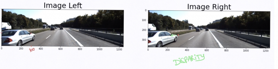
Img: Example of Disparity
- In the above example, if we take the side mirror on the left image at pixel (300, 175), we can find it on the right image at pixel (250, 175).
- In this example, xL = 300 and xR = 250. The disparity is called xL-xR; or here 50 pixels. It is estimated by sending two images to a function.
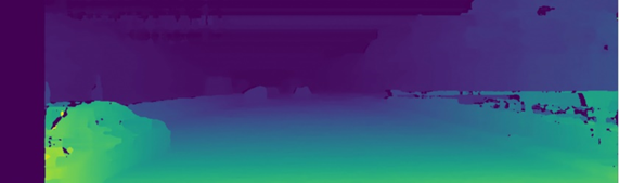
- Computing this for every pixel will get us a disparity map. Generally, close objects are lighter than far away objects that are represented in darker colors. We can see an example in the image below.
- To compute the disparity, we must find every pixel from the left image and match it to every pixel in the right image. This is called Stereo Matching. This is generally done in two steps:
- A pixel is taken in the left image
- Now, to find this pixel in the right image, it is searched along the epipolar line. There is no need for a 2D search, the point should be located on this line and the search is narrowed to 1D. This is because of the same height of the cameras as they are aligned along the same axis. We can see an example of this in the image below.
Img: Example of Stereo Matching using Epipolar line
4. Depth Mapping:
- In this step, we’ll compute a Depth Map
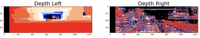
- We have two disparity maps, one for the left image and one for the right image that tells us basically what is the shift in pixels between two images, as we can also see in the image below.
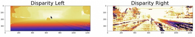
Img: Disparity Maps
- We can now generate the depth map.
- The depth map will tell us the distance of each pixel in an image, using the other image and the disparity map.
- Computation is done on each pixel using the stereo vision formula, and we get a depth map. We can see an example in the image below.
Img: Depth Maps
5. Obstacle Distance Estimation:
- In this step, we locate the objects in 3D, and match them with the Depth Map
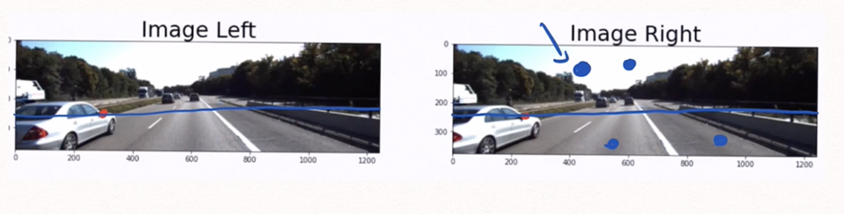
- We have a depth map for each camera. Now, combining this with obstacle detection algorithms such as YOLO will return, for every obstacle, a bounding box with 4 numbers: [x1; y1; x2; y2]. These numbers represent the coordinates of the upper left point and the bottom right point of the box.
- We can run this algorithm on the left image for example, and then use the left depth map.
- Now, in that bounding box, we can take the closest point. We know it, because we know the distance of every single point of the image thanks to the depth map. The first point in the bounding box will be our distance to the obstacle. We can also see an example in the image below.
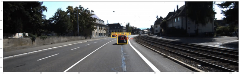
Img: Object Detection and Depth Estimation
This is how we can build a stereo vision system. With stereo vision, we can not only detect the obstacles in the image, but also their distance to the car.
You can learn more from here: Simple Stereo | Camera Calibration Stereo Vision | Student Competition: Computer Vision Training Stereo Vision and Depth Estimation - Computer Vision and OpenCV C++ and Python
Recently, deep learning has been increasingly used to solve stereo vision problems due to the predominating performance. However, deep learning for stereo vision is still at its infancy due to its unique challenges and varying pipelines. Lack of training data is another challenge for deep learning methods.
Another difficulty of the stereo vision task is the assumption that materials, viewpoints and lighting are known. If these are not known, the problem is generally ill-posed since multiple combinations of geometry, materials, viewpoints, and lighting can produce exactly the same photographs.
Summary
Stereo vision is the extraction of depth or 3D information from digital images. By comparing information about a scene from two cameras placed at two different points, 3D information can be extracted by examining the relative positions of objects in the two images.
Stereo cameras are crucial sensors for self-driving vehicles as they are low-cost and can be used to estimate depth, which is very necessary for the self-driving car to understand its surroundings accurately. It can be used for multiple purposes, such as object detection, depth estimation, etc.
Stereo vision has been prevalently applied in autonomous cars for depth perception. The two key aspects of computer stereo vision are speed and accuracy. They are two desirable but conflicting properties, the algorithms with better disparity accuracy usually have higher computational complexity. Improving the trade-off between speed and accuracy in stereo vision algorithms is an area of research.
Stereo estimation has shown great progress in the last years both in terms of accuracy and efficiency.
Stereo matching is equivalent to searching for correspondences in two images based on the assumption of constant appearance. However, appearance frequently changes due to non-rigidity or illumination changes.
Furthermore, saturated pixels, occluded regions, or pixels leaving the frame cannot be matched. Therefore, failure in those cases is inevitable for methods that solely rely on appearance matching without any other prior assumptions about the geometry.
The most common examples of failure cases in the autonomous driving context are car surfaces that cause appearance changes due to their shiny and reflective nature. Similarly, windows that are reflective and transparent cannot be matched reliably.
Occlusions are another source of error and require geometric reasoning beyond matching. Other examples of problematic regions include thin structures like traffic signs or repetitions as caused by fences.
The dream of safe self-driving cars can be truly realized only after we overcome all such challenges.

Simplify Your Data Annotation Workflow With Proven Strategies
.png)